doi: 10.56294/dm2023127
ORIGINAL
Creation of a soft circular patch antenna for 5G at a frequency of 2.45 GHz dedicated to biomedical applications
Creación de una antena de parche circular blando para 5G a una frecuencia de 2,45 GHz dedicada a aplicaciones biomédicas
Salah-Eddine Didi1, Imane Halkhams2, Abdelhafid Es-Saqy1, Mohammed Fattah3, Younes Balboul1, Said Mazer1, Moulhime El Bekkali1
1IASSE Laboratory, Sidi Mohamed Ben Abdellah University, Fez, Morocco.
2SIEDD Laboratory, UPF, Fez, Morocco.
3IMAGE Laboratory, Moulay Ismail University, Meknes, Morocco.
Cite as: Didi S-E, Halkhams I, Es-Saqy A, Fattah M, Balboul Y, Mazer S, El Bekkali M. Creation of a soft circular patch antenna for 5G at a frequency of 2.45 GHz dedicated to biomedical applications. Data and Metadata. 2023;2:127. https://doi.org/10.56294/dm2023127
Submitted: 09-08-2023 Revised: 15-10-2023 Accepted: 27-11-2023 Published: 28-12-2023
Editor: Prof.
Dr. Javier González Argote ![]()
Guest Editor:
Yousef Farhaoui ![]()
Note: Paper presented at the International Conference on Artificial Intelligence and Smart Environments (ICAISE’2023).
ABSTRACT
Telemedicine technology is one of the key achievements of recent years. This technology is based on biomedical devices that contain essential components, in-cluding antennas. Biomedical antennas ensure the exchange of data between de-vices installed on the human body and the external environment. This paper pre-sents the study and design of a flexible circular patch antenna implanted on a bio-sourced substrate for industrial, scientific, and medical applications. The frequen-cy chosen for the study is 2,45GHz. Return loss and radiation pattern measure-ments. An improvement in the gain of this antenna is also investigated in this study. This antenna offers adequate performance to meet the needs of 5G users. This antenna is printed on a polyester substrate with a thickness of h=2,85cm, a relative permittivity εr=3,2, a loss tangent equal to 0,003, and a patch radius equal to 2,11cm. In addition, this antenna provides the following results: reflection co-efficient S11=-26,59dB, bandwidth BW=0,12GHz, gain G=5,6, directivity D=5,8dB, and efficiency η=96,55 %.
Keywords: 5G; Antenna Soft; 2,45GHz; HFSS; Slot; ISM; GND.
RESUMEN
La tecnología de la telemedicina es uno de los principales logros de los últimos años. Esta tecnología se basa en dispositivos biomédicos que contienen componentes esenciales, entre ellos las antenas. Las antenas biomédicas garantizan el intercambio de datos entre los dispositivos instalados en el cuerpo humano y el entorno exterior. Este artículo presenta el estudio y diseño de una antena de parche circular flexible implantada en un sustrato de origen biológico para aplicaciones industriales, científicas y médicas. La frecuencia elegida para el estudio es de 2,45 GHz. Mediciones de pérdidas de retorno y diagrama de radiación. En este estudio también se investiga una mejora en la ganancia de esta antena. Esta antena ofrece unas prestaciones adecuadas para satisfacer las necesidades de los usuarios 5G. Esta antena está impresa en un sustrato de poliéster con un espesor de h=2,85cm, una permitividad relativa εr=3,2, una tangente de pérdida igual a 0,003, y un radio de parche igual a 2,11cm. Además, esta antena proporciona los siguientes resultados: coeficiente de reflexión S11=-26,59dB, ancho de banda BW=0,12GHz, ganancia G=5,6, directividad D=5,8dB, y eficiencia η=96,55 %.
Palabras clave: 5G, Antena Soft, 2,45GHz, HFSS, Slot, ISM, GND.
INTRODUCTION
Due to the rapid growth in the number of users connected to the Internet, as well as the rise of new information processing technologies such as artificial intelligence, the Internet of Things (IoT) and automation, data creation is increasing dramatically. Over the next decade, the quantity and volume of data flow will increase phenomenally, surely reaching hundreds of Zettabytes. Indeed, 5G enables users to communicate securely with each other. In addition, modern mobile infrastructures need to be regularly upgraded, as they are not adapted to this type of data flow.(1,2) At the same time, because of its speed, high capacity, and low reaction time, 5G technology can help support and develop many disciplines, including cloud-connected traffic control, drone delivery, online video chat, and console-quality gaming on the move. From global payments and critical situation response to e-learning and workers on the move, and right through to employee mobility, the benefits, as well as the possible uses of 5G technology, know no boundaries. It can potentially transform the world of work, the global economy, and people's lives.(3,4)
Due to contagious diseases and serious pandemics that have weakened the healthcare system and direct patient diagnosis in recent years, an alternative solution is needed. Telemedicine is one of the components of medicine that transmits medical data by means of electronic devices. Antennas are among the most important com-ponents, which in turn are responsible for transmitting medical information from the patient to the outside environment. Medical antennas are placed on the human body according to their tasks, including implantable in the human body to transmit information on the patient's state of health to the doctor to provide remote diagnosis, which motivates the human body to act as a pacemaker.(5,6) In addition, there are tissue antennas placed on clothing. These antennas operate in the ISM (Industrial, Scientific, and Medical bands) 902,8 - 928MHz and 2,4 - 2,5GHz.
The development of space telecommunications and remote monitoring and control has led to a growing need for low-cost, space-saving microwave devices based on simple, low-cost technology. Microwave systems with a microstrip structure have been at the origin of the development of printed antennas (patch or plate antennas), which are most often used in arrays to improve their performance and enable the realization of particular functions. Today, printed arrays are widely used, since they can be used to meet a wide range of system requirements. It is characterized by its radiation pattern, characteristic function, aperture angle, antenna dynamics, gain, and directivity. The main applications for these antennas can be found in numerous communication systems, such as mobile telephony, wireless multimedia systems (WIFI, Bluetooth), and space communications. They are also used in radar and re-mote detection systems, in frequency bands ranging from 1 GHz to millimeter bands. These applications are subject to selective criteria and limitations regarding weight, volume, and thickness.
An antenna with printed radiating elements, commonly called a "patch antenna," is a MICRORUBAN (MICROSTRIP) line of a particular shape. It consists of a ground plane and a dielectric substrate, the surface of which carries one or more metallic elements. They are lightweight, compact, low-cost, and have a planar configuration compatible with integrated circuits and, if required, conformable. Plated antennas are now used almost everywhere in mobile communications systems. These antennas are lightweight, space-saving, and inexpensive. They are manufactured using the photolithographic technique of printed circuit boards. Depending on the application, there are different shapes of radiating elements, types of substrate, and types of feed.(7,8)
Circular patch antennas have many uses in the medical, military, mobile, and satellite communications sectors. An antenna can be defined simply as a metal infra-structure for transmitting and receiving electromagnetic and radio waves and for converting electrical energy into electromagnetic waves at the transmitting unit, while the reverse occurs at the receiving unit. These antennas have become very common because of their small size, ease of production, and low cost, especially in wireless applications. The most common antennas are circular or rectangular because of their exciting radiation possibilities and ease of analysis. As a result, these antennas find many uses in portable devices such as cell phones.(9,10) Portable antennas have attracted much attention recently due to their many advantages, including ro-bust and inexpensive. They also have applications in the wireless communications and motion sensing sectors.(11,12)
In work,(13) we found a planar unipolar antenna etched on a MgTa1.5Nb0.5O6 substrate with dielectric constant εr = 28 and a thickness of 1mm. Another aluminum oxide (Al2O3) ceramic substrate, with a dielectric constant of 9,8 and a thickness of 0,4mm, was mounted above the antenna to insulate the metal parts to protect hu-man tissue. The volume of this antenna is 19,5×15×1,4 mm3. A coplanar transmission line also feeds it. Moreover, this antenna operates in the 402 MHz band and has produced performances such as a reflection coefficient of -43dB, a SAR value of 327 w/Kg, and an almost omnidirectional radiation pattern. In reference,(14) an implantable patch antenna was proposed for biomedical applications. This V-shaped monopole antenna is printed on an FR4 substrate and measures 33×28 mm2 with relative permittivity εr = 4,4 and thickness = 1,6 mm. The antenna consists of two ground planes and a patch fed by a coplanar waveguide. It operates in two bands, covering the ISM band (band 1: 900 to 915 MHz, band 2: 2370 to 2550 MHz). The antenna proposed in(15) is designed for biomedical applications. This patch antenna consists of the following basic elements: radiating element, feed line (CPW) and two GNDs (deformation of the ground plane). All these components are printed on a polyamide substrate (r=3,5, δ=0,008), with a total size of 24×22×0,07 mm3. This antenna resonates at 2,41 GHz with a reflection coefficient of -25dB, and the maximum SAR is observed at 0,914 W/Kg. In reference,(16) we found a miniaturized dual-band implantable antenna operating in the ISM band (902-928 MHz and 2,4-2,4835 GHz). Rogers ULTRALAM liquid-crystalline polymer with relative permittivity (εr = 2,9) and a thickness of 0,1 mm was used as both substrate and superstrate. The antenna has a total volume of 10,08 mm3 (7×7,2×0,2 mm3). In reference,(17) Piyush Kumar Mishra et al. proposed an implantable miniaturized patch antenna that operates in the ISM band (2,40-2,50 GHz). The total volume of this antenna is 127 mm3 (10×10×1,270 mm³). It is printed on a Rogers 6010 substrate (εr = 10,2 and height = 0,635 mm). To protect human tissue from the metal, a superstrate has been added to the top of the antenna. This antenna operates in the frequency range of 2,245 to 2,815 GHz, and the S11 reflection coefficient is equal to -34,856 dB at 2,455 GHz, covering the ISM band. The average SAR value obtained from this antenna is 621,97 W/kg for 1g of tissue. In article,(18) a microstrip textile patch antenna. This antenna is designed for medical applications (operating in the 2,45 GHz ISM band). The total volume of the antenna is 90×70×1,57 mm3. It comprises a ground plane and a patch fed by a CPW coplanar waveguide. All these elements are printed on a denim substrate with a relative permittivity of εr = 1,6 and a thickness of 62 mm. This covers the frequency range from 2,1 to 2,6 GHz with an S11 of -18 dB. A new dual-band portable antenna has been proposed in reference(19) for medical applications (2,4 GHz). Its structure consists of two substrates: a rigid substrate for the main radiating element and a substrate for the ground plane. The ring-shaped antenna is printed on a Taconic TLY-5 substrate with a dielectric constant of 2,2, a loss tangent of 0,0009, and a thickness of 1,52 mm. The Shieldit TMsuper ground plane is printed under the patch substrate with a thickness of 3mm. This antenna was fed by coaxial cable, with a total antenna volume of 60× 60 mm2. The characteristics of the proposed antenna are practically high gain (between 4,9 and 5,1 dB) and very high efficiency (reaching 91 %), with a SAR at 2,45 GHz of 0,2 W/kg under 1 g of tissue and 0,1 W/kg under 10 g, which is relatively low compared with other communication antennas.
According to the type of application, antennas can be produced using a variety of supports. When it comes to garment applications, textiles are attractive because they can be easily integrated into fabrics. Most paper substrates, easily accessible and inexpensive, are also attractive for ecological products. However, the most commonly used substrates are polymer-based. The most common are polyimide (Kapton), polyethylene terephthalate (PET), and polydimethylsiloxane (PDMS).20,21,22 The main drawback of these materials is that they are obtained from petroleum ex-tracts. As a result, there is growing interest in alternatives that reduce the need for such materials, hence the dependence on oil and the ecological footprint of electronic devices. In this context, we propose using a biobased polymer as a substrate for a circular patch antenna operating at 2,45 GHz. We use this frequency band (2,45 GHz), as it is widely used in industry and is included in the IMS (Industrial, Medical and Scientific) band. In fact, the 300 MHz to 2,5 GHz bandwidth is reserved for industrial, medical and scientific applications, such as sensor networks and remote guidance, for example. The 2,45 GHz frequency, for example, is used by microwave ovens to heat food. In Europe, this frequency band is known as the SRD band for "Short-Range Devices". To use this frequency band, you don't need a license, but it is regulated nonetheless. Maximum transmission power and modulation types are regulated.
The aim of this study is to create a circular printed antenna with a very small volume and provide the best characteristics in terms of gain, s11, bandwidth, and efficiency, using two techniques. These are the deformation of the radiated element and the deformation of the ground plane(GND). In addition, the overall structure of the radiated element is a disk with a radius of 2,11 cm, missing two semicircles with a radius of 0,88 cm, as shown in figure 1. This antenna is dedicated to biomedical ap-plications. This work is organized as follows: We start with the introduction, then we present the design procedure for this antenna, then we simulate this antenna using HFSS simulation software, then we compare the results obtained by this antenna with the work available in scientific literature, and finally we end this work with the conclusion.
Circular patch antenna design method
To analyze a circular patch antenna, we need to use the cavity model technique. This analysis can be carried out using the same procedure as for rectangular antennas but in cylindrical coordinates. In addition, this cavity is made up of two perfect electrical conductors placed at the top and bottom in order to represent both the patch and the ground plane, and a cylindrical perfect magnetic conductor located at the circular periphery of the cavity. In addition, the dielectric material of the substrate is assumed to be truncated beyond the extent of the patch.(23)
The procedure for designing a circular microruban patch antenna is based on key parameters such as substrate dielectric constant (εr), resonant frequency (fr), and substrate height h. Using these parameters to determine antenna elements such as the effective patch radius Re, the real patch radius R, and the resonant frequency for the TMZ110 dominant. To achieve this, we use the formulas (1-4) below.(24,25) In this study, we choose a polyester substrate with a thickness of h=2,85cm, a relative per-mittivity εr=3,2, a loss tangent equal to 0,003, and a patch radius equal to 2,11cm. Indeed Polyester is a moisture-resistant and water-repellent substrate, which makes it more difficult to wet, thus preserving its electromagnetic properties. It helps suppress the antenna's surface waves to improve its radiation performance (gain, directivity). Polyester, on the other hand, is the most common textile used in clothing. Figure 1 illustrates the geometric structure of the proposed antenna. A microstrip line feeds this antenna. Furthermore, the numerical values of all the elements of this proposed antenna are listed in table 1.
· The actual patch radius is given by:

· Equation (1) does not take into account the marginal effect. Since the marginal effect makes the patch electrically larger, the effective patch radius is used and is given by:


· Consequently, the resonance frequency for the dominant TMZ110 dominant is indicated by:

· Where ν0 is the speed of light in free space.

Figure 1. Design antenna geometry

Figure 2. Graphical representation of S11

Figure 3. Graphical representation of VSWR
|
Table 1. The parameters of this antenna |
|||
|
Parameters |
Values(cm) |
Parameters |
Values(cm) |
|
R |
2,11 |
(L1-W1) |
(0,209-3,645) |
|
h |
2,85 |
(L2-W2) |
(0,674-3,195) |
|
(Ls-Ws) |
(11-10) |
|
|
RESULTS
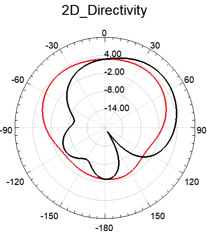
This antenna gives the following results: reflection coefficient S11=-26,59dB, band-width BW=0,12GHz, as shown in figure 2. In addition, it generates better radiation, particularly in terms of gain, which is 5,6 dB (this parameter is illustrated in figure 3), and directivity, which is 5,8 dB (this parameter is illustrated in Figure 4). All these results were obtained using the HFSS simulation tool. HFSS is a 3-D electromagnetic modeling software package, based on the harmonic finite element method (FEM). The software features a user-friendly graphical interface, making it easy to generate field maps in the calculation volume. What's more, it uses a frequency-based method that enables results to be obtained quickly at a single frequency point. However, in the particular case of studying the behavior of a cell as a function of frequency, the frequency method used obliges us to carry out a simulation per frequency point (without, however, recalculating the mesh, which is constant over the frequency band), which leads to long calculation times.
|
|
|
|
Figure 3. Graphical representation of gains in 3D and 2D |
|


|
|
|
|
Figure 4. Graphical representation of directivity in 3D and 2D |
|

Comparison of the results obtained with those available in the scientific literature
|
Table 2. A comparative study with other studies |
||||||
|
Ref |
Fr (GHz) |
S11 (dB) |
BW (MHz) |
Gain (dB) |
Direct (dB) |
η % |
|
(26) |
2,4 |
-47 |
51,4 |
4,24 |
- |
- |
|
(27) |
2,4 |
-13,89 |
70 |
6,6 |
- |
92,5 |
|
(28) |
2,4 |
-30 |
245,8 |
2,83 |
- |
- |
|
(29) |
2,4 |
-24,52 |
979 |
- |
- |
- |
|
(30) |
2,45 |
-20,4 |
74,6 |
2,6 |
7,47 |
34,69 |
|
AP |
2,45 |
-26,59 |
120 |
5,6 |
5,8 |
96,55 |
Table 2 compares the simulation results obtained with the proposed antenna (AP) with those currently available in the scientific literature. It can be visibly observed that the proposed antenna produces interesting results relative to other works in terms of bandwidth, gain, and efficiency, which is clearly shown in table 2. The bandwidth obtained by the proposed antenna is very high, in contrast to those obtained by works,(27,28,29,30) as is its efficiency. In addition, the reflection coefficient and bandwidth achieved by an antenna(26) are better than those achieved by other works, as shown in table 2.
CONCLUSION
This article presents a flexible patch antenna on a natural polymer substrate for ISM applications at 2,45 GHz. The shape of this radiated element (patch) is circular. The various characterizations carried out demonstrate its potential use for applications where mechanical flexibility is required. Moreover, the performance of the patch antenna, in particular gain and directivity, can be enhanced by integrating several patch resonators on a single substrate to form an array antenna.
The results show that this antenna and the proposed material are interesting candidates for developing flexible and green electronics, particularly in 5G systems. My prospect for the future is to improve this antenna and design a more efficient one.
REFERENCES
1. Allesandra, C., Diego. M.: Smart Solutions in Smart Spaces: Getting the Most from Far-Field Wireless Power Transfer. IEEE Microwave Magazine 17(5), 30-45(2016).
2. Abdelhafid, E., Maryam, A., Said, M., Mohammed, F., e al. : A pHEMT Double-Balanced Up-Conversion Mixer for 5G MM-Wave Communication Systems. IJMOT 17(4), 401-4011(2022).
3. Salah-Eddine, D., Imane, H., Mohammed, F., Younes, B., Said, M., Moulhime, EL.: Study and Design of a 5G Millimeter Band Patch Antenna with a Resonant Frequency of 60 GHz. Journal of Nano- and Electronic Physics 15(2), 02015-1-02015-6(2023).
4. Sugumari, T., Fusic, S.J., Cornelius, K.S.R.J. et al. Design and Analysis of Single-Fed Du-al-Mode Circular Parasitic Patch Antenna (CPPA) for UAV Application. SN COMPUT. SCI. 4, 247 (2023).
5. Xiao, C., Liang. Z., Yang. J.: Radiation Characteristic Analysis of Antenna Deeply Implant-ed in Human Body and Localization Sensor Array. IEEE Transactions on Instrumentation and Measurement Vol. 71. 2022.
6. AMER. A, OMAR. A. S, ASHRAF. A, SAMER A.: Design of LoRa Antenna for Weara-ble Medical Applications. IEEE Access Vol. 11. pp. 23886-23895(2023).
7. Salah-Eddine, D., Imane, H., Mohammed, F., Younes, B., Said, M., Moulhime, EL, Sudip-ta, D.: Study and Design of the Microstrip Patch Antenna Operating at 120 GHz. In: El Ghzaoui, M., Das, S., Lenka, T.R., Biswas, A. (eds) Terahertz Wireless Communication Components and System Technologies. pp. 175-190, Springer, Singapore (2022).
8. Auza-Santiváñez JC, Díaz JAC, Cruz OAV, Robles-Nina SM, Escalante CS, Huanca BA. mHealth in health systems: barriers to implementation. Health Leadership and Quality of Life 2022;1:7-7. https://doi.org/10.56294/hl20227.
9. Ali, H. K.: Implementation of a Circular Shape Patch Antenna at 2.4 GHz for Different Wireless Communications. Iraqi Journal of Science 64 (1), 205-214(2023).
10. Inasse. E, Anas. C, Salaheddine. K. A.: Modeling and Simulation of Transport and Biologi-cal Reaction in Fluid-Saturated Porous Media. International Review on Modelling and Simu-lations (IREMOS) Vol 15, No 3(3), pp. 197-202 (2022).
11. Pandey, S., Markam, K.: Design and Analysis of Circular Shape Microstrip Patch Antenna for C-band Applications. International Journal of Advanced Research in Computer Science & Technology 4, 169-171(2016).
12. Gonzalez-Argote J. Patterns in Leadership and Management Research: A Bibliometric Review. Health Leadership and Quality of Life 2022;1:10-10. https://doi.org/10.56294/hl202210.
13. Tsung-Fu. C, Hung-Chi. Y, Chien-Min. C, Ching-Hsing. L.: develop CPW-fed monopole broadband implantable antennas on high dielectric constant ceramic substrates. Microwave Opt Technol Lett, VOL. 52, No. 9, pp. 2136–2139(2010).
14. Ashok. A. S, Shanmuganantham. T: CPW fed monopole implantable antenna for 2.45 GHz ISM band applications. International Journal of Electronics Letters. june 2013.
15. Kumar Naik Ketavath et al.: In-Vitro Test of Miniaturized CPW-Fed Implantable Conformal Patch Antenna at ISM Band for Biomedical Applications, “ IEEE Access, VOL. 7, pp. 43547-43554(2019).
16. Faisal. F, Yoo. H.: A Miniaturized Novel-Shape Dual-BandAntenna for Implantable Appli-cations. IEEE TRANSACTIONS ON ANTENNAS AND PROPAGATION, VOL. 67, NO. 2(2019).
17. Piyush Kumar Mishra et al.: A Novel Skin-Implantable Patch Antenna For Biomedical Ap-plications. International Conference on Electrical, 2020.
18. Sreelakshmy. R, Ashok Kumar. S, Shanmuganantham. T.: A wearable type embroidered logo antenna at ISM band for military applications. Microw Opt Technol Lett, VOL. 59, pp. 2159–2163( 2017).
19. Tuan Le. T, Tae-Yeoul. Yun.: Wearable Dual-Band High-Gain Low-SAR Antenna for Off-Body Communication. IEEE Antennas and Wireless Propagation Letters, VOL. 20, 2021.
20. Ibanez Labiano, Alomainy, A.: Flexible inkjet-printed graphene antenna on Kapton. Flex. Print. Electron 6(2), 1-9(2021).
21. Xu, D., Xu, R., Hu, B. et al. Flexible low-profile UWB antenna on polyimide film based on silver nanoparticle direct-write dispenser printing for wireless applications. Journal of Mate-rials Science: Materials in Electronics 34(1297), (2023).
22. Salah-Eddine, D., Imane, H., Mohammed, F., Younes, B., Said, M., Moulhime, EL.: Design of a Microstrip Antenna Two-Slot for Fifth Generation Applications operating at 27.5GHz. International Conference on Digital Technologies and Applications(ICDTA), Lecture Notes in Networks and Systems, Fes, Morocco, vol 211, pp. 1081-1089. Springer (2021).
23. Balanis C.A(1982) Handbook of Microstrip Antennas. John Wiley and Sons New York.
24. Babatunde, S., Latujoye, O., Jeffrey, C. S, : Design and Performance Analysis of 4-Element Multiband Circular Microstrip Antenna Array for Wireless Communications. IOSR Journal of Electronics and Communication Engineering (IOSR-JECE) 18(1), 01-07(2023).
25. Salah-Eddine, D., Imane, H., Abdelhafid, E., Mohammed, F., Younes, B., Said, M., Moulhime, EL. New microstrip patch antenna array design at 28 GHz millimeter-wave for fifth-generation application. IJECE 13(4), 4184~4193(2023).
26. Ali, H. K.: Implementation of a Circular Shape Patch Antenna at 2.4 GHz for Different Wireless Communications. Iraqi Journal of Science 25 (4), 54-58(2022).
27. Sohel, R. Md., Mostafizur, R. Md.: Study of Microstrip Patch Antenna for Wireless Com-munication System. In: 2022 International Conference for Advancement in Technology (ICONAT), pp. 1-4. IEEE, Goa, India (2022).
28. Gökçen, D., Cem, G., Ismail, A.: MICRO-STRIP PATCH 2.4 GHz Wi-Fi ANTENNA DESIGN FOR WLAN 4G- 5G APPLICATION. International Journal of Surveys, Engi-neering and Technology 6(1), 68-72(2022).
29. Cem, G., Sena, E. B. K., Rukiye, B. A.: The Development of Broadband Microstrip Patch Antenna for Wireless Applications. BİTLİS EREN UNIVERSITY JOURNAL OF SCIENCE 11(3), 812-819(2022).
30. Md. Sohel Rana, Bijoy Kumer Sen, Md. Tanjil-Al Mamun, Md. Shahriar Mahmud, Md. Mostafizur Rahman.: A 2.45 GHz microstrip patch antenna design, simulation, and analysis for wireless applications. Bulletin of Electrical Engineering and Informatics 12(4), 2173~2184(2023).
FINANCING
The authors did not receive financing for the development of this research.
CONFLICT OF INTEREST
None.
AUTHORSHIP CONTRIBUTION
Conceptualization: Salah-Eddine Didi, Imane Halkhams, Abdelhafid Es-Saqy, Mohammed Fattah, Younes Balboul, Said Mazer, Moulhime El Bekkali.
Research: Salah-Eddine Didi, Imane Halkhams, Abdelhafid Es-Saqy, Mohammed Fattah, Younes Balboul, Said Mazer, Moulhime El Bekkali.
Drafting - original draft: Salah-Eddine Didi, Imane Halkhams, Abdelhafid Es-Saqy, Mohammed Fattah, Younes Balboul, Said Mazer, Moulhime El Bekkali.
Writing - proofreading and editing: Salah-Eddine Didi, Imane Halkhams, Abdelhafid Es-Saqy, Mohammed Fattah, Younes Balboul, Said Mazer, Moulhime El Bekkali.